Air Circuit Breakers
Make electrical equipment multi-functional by means of Mitsubishi air circuit breakers that are suitable for protection of the main circuit.
Air circuit breakers have many advantages, among them adding higher reliability during switching. They can be used to extend the area of selective coordination trough expansion of the rated short-time withstand current, for use in main circuit ports.
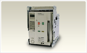
Air Circuit Breakers (ACB) AE-SW

This kind of breaker is used as the main power breaker of the supply such as buildings, factories and ships etc. and satisfy the various needs.
Product Specification:
|
SUPER AE – WORLD SUPER SERIES |
AE1000-SW |
AE1250-SW |
AE1600-SW |
AE2000-SWA |
||||
|---|---|---|---|---|---|---|---|---|
|
Frame size |
A |
1000 |
1250 |
1600 |
2000 |
|||
|
Rated insulation voltage (AC V) 50/60 Hz |
U i |
1000 |
||||||
|
Rated operating voltage (AC V) 50/60 Hz |
U e |
690 |
||||||
|
Rated impulse withstand voltage (kV) |
U imp |
12 |
||||||
|
Pollution degree |
3 |
|||||||
|
Number of poles |
P |
3 / 4 |
3 / 4 |
3 / 4 |
3 / 4 |
|||
|
Rated curren t I n (CT rating) |
1000 |
1250 |
1600 |
2000 |
||||
|
Adjustment range Rated current I r (A) |
General use (current rating adjustable 0.5 to 1.0 x I n 0.05 step) |
500-550-600-650- 700-750-800-850- 900-950 -1000 |
625-687.5-750-812.5- 875-937.5-1000-1062.5-1125-1187.5-1250 |
800-880-960-1040- 1120-1200-1280-1360- 1440-1520-1600 |
1000-1100-1200-1300- 1400-1500-1600-1700- 1800-1900-2000 |
|||
|
Generator protection(current rating fixed) |
400 ≤ I r ≤ 1000 |
800 ≤ I r ≤ 1250 |
1000 ≤ I r ≤ 1600 |
1250 ≤ I r ≤ 2000 |
||||
|
Rated current of neutral pole |
A |
1000 |
1250 |
1600 |
2000 |
|||
|
IEC 60947-2, EN 60947-2, VDE, JIS C 8201-2-1 |
Ultimate breaking capacity I cu (kA rms) |
690 V AC |
65 |
65 |
65 |
65 |
||
|
600 V AC |
65 |
65 |
65 |
65 |
||||
|
240–500 V AC |
65 |
65 |
65 |
65 |
||||
|
With MCR |
690 V AC |
65 |
65 |
65 |
65 |
|||
|
600 V AC |
65 |
65 |
65 |
65 |
||||
|
240–500 V AC |
65 |
65 |
65 |
65 |
||||
|
Withoutinstantaneous |
690 V AC |
25 a |
25 a |
25 a |
25 a |
|||
|
500 V AC |
25 a |
25 a |
25 a |
25 a |
||||
|
Rated service breaking capacity Ics (kA rms) % lcu |
||||||||
|
Rated making capacity I cm (kA, peak) |
690 V AC |
143 |
143 |
143 |
143 |
|||
|
600 V AC |
143 |
143 |
143 |
143 |
||||
|
240–500 V AC |
143 |
143 |
143 |
143 |
||||
|
With MCR |
690 V AC |
143 |
143 |
143 |
143 |
|||
|
600 V AC |
143 |
143 |
143 |
143 |
||||
|
240–500 V AC |
143 |
143 |
143 |
143 |
||||
|
Withoutinstantaneous |
690 V AC |
52.5 |
52.5 |
52.5 |
52.5 |
|||
|
500 V AC |
52.5 |
52.5 |
52.5 |
52.5 |
||||
|
Disconnector: switching capacity (6x I r at 690V AC) |
O |
O |
O |
O |
||||
|
Rated short time withstand current (kA rms) I cw |
1 s |
65 |
65 |
65 |
65 |
|||
|
2 s |
60 |
60 |
60 |
60 |
||||
|
3 s |
50 |
50 |
50 |
50 |
||||
|
Maximum total breaking time |
ms |
40 f |
40 f |
40 f |
40 f |
|||
|
Closing time |
ms |
80 |
80 |
80 |
80 |
|||
|
Number of operating cycles (ON/OFF) b |
With ratedcurrent |
500 V AC I n |
5000 |
5000 |
5000 |
1500 |
||
|
690 V AC I n |
5000 |
5000 |
5000 |
1500 |
||||
|
Without rated current d |
25000 |
25000 |
25000 |
25000 |
||||
|
Connecting terminal |
Horizontal terminal |
O |
O |
O |
— |
|||
|
Vertical terminal |
O |
O |
O |
O c |
||||
|
Front terminal |
O |
O |
O |
— |
||||
|
Dimensions (HxWxD) mm |
Fixed type |
3-pole |
410x340x290 |
|||||
|
4-pole |
410x425x290 |
|||||||
|
Drawout type |
3-pole |
430x300x368 |
||||||
|
4-pole |
430x385x368 |
|||||||
|
Weight kg |
Fixed type |
3-pole |
41 |
41 |
42 |
47 |
||
|
4-pole |
51 |
51 |
52 |
57 |
||||
|
Drawout type(with cradle) |
3-pole |
64 |
64 |
65 |
70 |
|||
|
4-pole |
78 |
78 |
79 |
84 |
||||
|
Cradle only |
3-pole |
26 |
26 |
26 |
31 |
|||
|
4-pole |
30 |
30 |
30 |
35 |
||||
- The columns for “without instantaneous” are the values when the bare main body and the external relay is combined.
- The number of operating cycles without rated current also include the number of operating cycles with rated current.
- AE4000-SW, AE5000-SW, AE6300-SW, AE2000-SWA and AE4000-SWA apply for only vertical terminal of connecting terminal.
- This value means number of operating cycles of ACB's body not including accessories.
- Products with low rating types is available.
|
SUPER AE – WORLD SUPER SERIES |
AE2000-SW |
AE2500-SW |
AE3200-SW |
AE4000-SWA |
AE4000-SW |
AE5000-SW |
AE6300-SW |
||||
|---|---|---|---|---|---|---|---|---|---|---|---|
|
Frame size |
A |
2000 |
2500 |
3200 |
4000 |
4000 |
5000 |
6300 |
|||
|
Rated insulation voltage (AC V) 50/60 Hz |
U i |
1000 |
1000 |
||||||||
|
Rated operating voltage (AC V) 50/60 Hz |
U e |
690 |
690 |
||||||||
|
Rated impulse withstand voltage (kV) |
Uimp |
12 |
12 |
||||||||
|
Pollution degree |
3 |
3 |
|||||||||
|
Number of poles |
P |
3 / 4 |
3 / 4 |
3 / 4 |
3 / 4 |
3 / 4(HN, FN) g |
3 / 4(HN, FN) g |
3 / 4(HN, FN) g |
|||
|
Rated curren t I n (CT rating) |
2000 |
2500 |
3200 |
4000 |
4000 |
5000 |
6300 |
||||
|
Adjustment range Rated current I r (A) |
General use (current rating adjustable 0.5 to 1.0 x I n 0.05 step) |
1000-1100-1200-1300- 1400-1500-1600-1700- 1800-1900-2000 e |
1250-1375-1500-1625- 1750-1875-2000-2125- 2250-2375-2500 |
1600-1760-1920-2080- 2240-2400-2560-2720- 2880-3040-3200 |
2000-2200-2400-2600- 2800-3000-3200-3400- 3600-3800-4000 |
2000-2200-2400-2600- 2800-3000-3200-3400- 3600-3800-4000 |
2500-2750-3000-3250- 3500-3750-4000-4250- 4500-4750-5000 |
3150-3465-3780-4095- 4410-4725-5040-5355- 5670-5985-6300 |
|||
|
Generator protection(current rating fixed) |
800 ≤ I r ≤ 2000 |
1600 ≤ I r ≤ 2500 |
2000 ≤ I r ≤ 3200 |
2500 ≤ I r ≤ 4000 |
2500 ≤ I r ≤ 4000 |
3150 ≤ I r ≤ 5000 |
4000 ≤ I r ≤ 6300 |
||||
|
Rated current of neutral pole |
A |
2000 |
2500 |
3200 |
4000 |
2000 (4000) h |
2500 (5000) h |
3150 (6300) h |
|||
|
IEC 60947-2,EN 60947-2,VDE, JIS C 8201-2-1 |
Ultimate breaking capacity Icu (kA rms) |
690 V AC |
75 |
75 |
75 |
75 |
85 |
85 |
85 |
||
|
600 V AC |
75 |
75 |
75 |
75 |
85 |
85 |
85 |
||||
|
240–500 V AC |
85 |
85 |
85 |
85 |
130 |
130 |
130 |
||||
|
With MCR |
690 V AC |
75 |
75 |
75 |
75 |
85 |
85 |
85 |
|||
|
600 V AC |
75 |
75 |
75 |
75 |
85 |
85 |
85 |
||||
|
240–500 V AC |
75 |
75 |
75 |
75 |
100 |
100 |
100 |
||||
|
Withoutinstantaneous |
690 V AC |
45 a |
45 a |
45 a |
45 a |
65 a |
65 a |
65 a |
|||
|
500 V AC |
45 a |
45 a |
45 a |
45 a |
65 a |
65 a |
65 a |
||||
|
Rated service breaking capacity Ics (kA rms) % l cu |
100 % |
100 % |
|||||||||
|
Rated making capacity Icm (kA, peak) |
690 V AC |
165 |
165 |
165 |
165 |
187 |
187 |
187 |
|||
|
600 V AC |
165 |
165 |
165 |
165 |
187 |
187 |
187 |
||||
|
240–500 V AC |
187 |
187 |
187 |
187 |
286 |
286 |
286 |
||||
|
With MCR |
690 V AC |
165 |
165 |
165 |
165 |
187 |
187 |
187 |
|||
|
600 V AC |
165 |
165 |
165 |
165 |
187 |
187 |
187 |
||||
|
240–500 V AC |
165 |
165 |
165 |
165 |
220 |
220 |
220 |
||||
|
Withoutinstantaneous |
690 V AC |
94.5 |
94.5 |
94.5 |
94.5 |
143 |
143 |
143 |
|||
|
500 V AC |
94.5 |
94.5 |
94.5 |
94.5 |
143 |
143 |
143 |
||||
|
Disconnector: switching capacity (6x I r at 690V AC) |
O |
O |
O |
O |
O |
O |
O |
||||
|
Rated short time withstand current (kA rms) I cw |
1 s |
75 |
75 |
75 |
75 |
100 |
100 |
100 |
|||
|
2 s |
75 |
75 |
75 |
75 |
85 |
85 |
85 |
||||
|
3 s |
65 |
65 |
65 |
65 |
85 |
85 |
85 |
||||
|
Maximum total breaking time |
ms |
40 f |
40 f |
40 f |
40 f |
50 f |
50 f |
50 f |
|||
|
Closing time |
ms |
80 |
80 |
80 |
80 |
80 |
80 |
80 |
|||
|
Number of operating cycles(ON/OFF) b |
With ratedcurrent |
500 V AC In |
1500 |
1500 |
1000 |
500 |
1000 |
1000 |
1000 |
||
|
690 V AC In |
1500 |
1500 |
1000 |
500 |
1000 |
1000 |
1000 |
||||
|
Without rated current d |
20000 |
20000 |
20000 |
20000 |
10000 (3P)/5000 (4P) |
10000 (3P)/5000 (4P) |
10000 (3P)/5000 (4P) |
||||
|
Connecting terminal |
Horizontal terminal |
O |
O |
O |
— |
— |
— |
— |
|||
|
Vertical terminal |
O |
O |
O |
O c |
O c |
O c |
O c |
||||
|
Front terminal |
O |
O |
O |
— |
— |
— |
— |
||||
|
Dimensions (HxWxD) mm |
Fixed type |
3-pole |
410x475x290 |
414x873x290 |
|||||||
|
4-pole |
410x605x290 |
414x1003 (1133)x290 h |
|||||||||
|
Drawout type |
3-pole |
430x435x368 |
430x439x368 |
480x875x368 |
|||||||
|
4-pole |
430x565x368 |
430x569x368 |
480x1005 (1135)x368 h |
||||||||
|
Weight kg |
Fixed type |
3-pole |
60 |
61 |
63 |
81 |
160 |
160 |
160 |
||
|
4-pole |
72 |
73 |
75 |
99 |
180 (200) h |
180 (200) h |
180 (200) h |
||||
|
Drawout type(with cradle) |
3-pole |
92 |
93 |
95 |
108 |
233 |
233 |
240 |
|||
|
4-pole |
113 |
114 |
116 |
136 |
256 (279) h |
256 (279) h |
263 (286) h |
||||
|
Cradle only |
3-pole |
35 |
35 |
35 |
49 |
118 |
118 |
125 |
|||
|
4-pole |
43 |
43 |
43 |
61 |
133 (148) h |
133 (148) h |
140 (155) h |
||||
- f) This value means the instantaneous breaking time at short-circuit interruption. As for accessories (UVT, SHT)
- g) 4 (HN) means the neutral poles current capacity is 50 % of the rated current, for 4-poles.4 (FN) means the neutral poles current capacity is 100 % of the rated current, for 4-poles.
- h) () shows the value for 4P FN type.
- Remarks:– All models conform the isolating function according to IEC 60947-2.– Reverse connection is possible