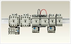
Wide selection of products that supports all types of applications.
MS-T/N Series Motor Starters are environmentally friendly, internationally usable, compact, easy to use and safe. They comply with many international standards, and cover a wide range of applications, from switchboards to machines requiring high reliability.
Contactors
Enables precise control for your motor.
Allows you to remotely control other loads than motors, such as heaters (resistors) and lighting loads.
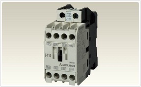
Non Reversing Contactors

Suitable for switching motors during start and stop.
Standard models comply with Japanese and many international standards.
Product Specification
|
Specifications |
S-T10AC_ _ _V1A |
S-T10AC_ _ _V1B |
S-T12AC_ _ _V1A1B |
S-T12AC_ _ _V2A |
S-T12AC_ _ _V2B |
S-T20AC_ _ _V1A1B |
S-T20AC_ _ _V2A |
S-T21AC_ _ _V2A2B |
S-T25AC_ _ _V2A2B |
S-T32AC_ _ _V |
||
|---|---|---|---|---|---|---|---|---|---|---|---|---|
|
Rated data |
||||||||||||
|
Applicable standard |
All types: IEC60947-4-1, EN60947-4-1, JIS C8201-4-1 |
|||||||||||
|
Rated insulation voltage |
V |
All types: 690 |
||||||||||
|
Rated impulse withstand voltage |
kV |
All types: 6 |
||||||||||
|
Rated frequency |
Hz |
All types: 50/60 |
||||||||||
|
Pollution degree |
All types: 3 |
|||||||||||
|
Rated operational power (current) Category AC-3 (Three-phase squirrel-cage motor load, standard responsibility) |
220–240 V |
kW (A) |
2.5 (11) |
2.5 (11) |
3.5 (13) |
3.5 (13) |
3.5 (13) |
4.5 (18) |
4.5 (18) |
5.5 (25) |
7.5 (30) |
7.5 (32) |
|
380–440 V |
kW (A) |
4 (9) |
4 (9) |
5.5 (12) |
5.5 (12) |
5.5 (12) |
7.5 (18) |
7.5 (18) |
11 (23) |
15 (30) |
15 (32) |
|
|
500 V |
kW (A) |
4 (7) |
4 (7) |
5.5 (9) |
5.5 (9) |
5.5 (9) |
7.5 (17) |
7.5 (17) |
11 (17) |
15 (24) |
15 (24) |
|
|
690 V |
kW (A) |
4 (5) |
4 (5) |
5.5 (7) |
5.5 (7) |
5.5 (7) |
7.5 (9) |
7.5 (9) |
7.5 (9) |
11 (12) |
11 (12) |
|
|
Rated operational power (current) Category AC-4 (Three-phase squirrel-cage motor load, inching responsibility) |
220–240 V |
kW (A) |
1.5 (8) |
1.5 (8) |
2.2 (11) |
2.2 (11) |
2.2 (11) |
3.7 (18) |
3.7 (18) |
3.7 (18) |
4.5 (20) |
5.5 (26) |
|
380–440 V |
kW (A) |
2.2 (6) |
2.2 (6) |
4 (9) |
4 (9) |
4 (9) |
5.5 (13) |
5.5 (13) |
5.5 (13) |
7.5 (17) |
11 (24) |
|
|
500 V |
kW (A) |
2.7 (6) |
2.7 (6) |
5.5 (9) |
5.5 (9) |
5.5 (9) |
5.5 (10) |
5.5 (10) |
5.5 (10) |
7.5 (12) |
7.5 (13) |
|
|
Rated operational power (current) Category AC-1(Resistance, heater load) |
100–240 V |
kW (A) |
20 |
20 |
20 |
20 |
20 |
20 |
20 |
32 |
32 |
32 |
|
380–440 V |
kW (A) |
11 |
11 |
13 |
13 |
13 |
13 |
13 |
32 |
32 |
32 |
|
|
Conventional free air thermal current Ith |
A |
20 |
20 |
20 |
20 |
20 |
20 |
20 |
32 |
32 |
32 |
|
|
Minimum applicable load level |
All types: 48 V 200 mA |
|||||||||||
|
Auxiliary contact rating |
||||||||||||
|
Contact arrangement |
Standard |
1 NO |
1 NC |
1 NO + 1 NC |
2 NO |
2 NC |
1 NO + 1 NC |
2 NO |
2 NC |
2 NO + 2 NC |
— |
|
|
Max. number of additional options a |
Front clip-on |
pcs. |
1 |
1 |
1 |
1 |
1 |
1 |
1 |
1 |
1 |
1 |
|
Side clip-on |
pcs. |
2 |
2 |
2 |
2 |
2 |
2 |
2 |
2 |
2 |
2 |
|
|
Rated operational current (Category AC-15 : Alternating current coil load) |
120 V |
A |
6 |
6 |
6 |
6 |
6 |
6 |
6 |
6 |
6 |
6 |
|
240 V |
A |
3 |
3 |
3 |
3 |
3 |
3 |
3 |
3 |
3 |
3 |
|
|
Rated operational current (Category DC-13 : Direct current coil load) |
24 V |
A |
3 |
3 |
3 |
3 |
3 |
3 |
3 |
3 |
3 |
3 |
|
110 V |
A |
0.6 |
0.6 |
0.6 |
0.6 |
0.6 |
0.6 |
0.6 |
0.6 |
0.6 |
0.6 |
|
|
Conventional free air thermal current Ith |
A |
10 |
10 |
10 |
10 |
10 |
10 |
10 |
10 |
10 |
10 |
|
|
Minimum applicable load level |
All types: 20 V 3 mA |
|||||||||||
|
Performance |
||||||||||||
|
Mechanical durability [ten thousand times] |
All types: 1,000 |
|||||||||||
|
Electrical durability [ten thousand times] |
Please refer to the Electrical durability curve |
|||||||||||
|
Switching frequency [times/hour] |
Category AC-3 |
1800 |
1800 |
1800 |
1800 |
1800 |
1800 |
1800 |
1800 |
1800 |
1800 |
|
|
Category AC-4 |
300 |
300 |
300 |
300 |
300 |
300 |
300 |
300 |
300 |
300 |
||
|
Category AC-1 |
1200 |
1200 |
1200 |
1200 |
1200 |
1200 |
1200 |
1200 |
1200 |
1200 |
||
|
Coil consumption (at rated coil voltage) c |
Inrush |
(VA) |
45 |
45 |
45 |
45 |
45 |
45 |
45 |
75 |
75 |
55 |
|
Sealed |
(VA) |
7 |
7 |
7 |
7 |
7 |
7 |
7 |
6 |
6 |
4.5 |
|
|
Watts |
(W) |
2.2 |
2.2 |
2.2 |
2.2 |
2.2 |
2.2 |
2.2 |
2.4 |
2.4 |
1.8 |
|
|
Mechanical data |
||||||||||||
|
Dimensions (WxHxD) |
mm |
36x75x78 |
36x75x78 |
43x75x78 |
43x75x78 |
43x75x78 |
43x75x78 |
43x75x78 |
63x81x81 |
63x81x81 |
43x81x81 |
|
|
Order information |
AC 24 V |
Art. no. |
279140 |
279197 |
279204 |
279211 |
279218 |
279225 |
279232 |
279239 |
279246 |
279253 |
|
AC 48 V |
279141 |
279198 |
279205 |
279212 |
279219 |
279226 |
279233 |
279240 |
279247 |
279254 |
||
|
AC 100 V |
279142 |
279199 |
279206 |
279213 |
279220 |
279227 |
279234 |
279241 |
279248 |
279255 |
||
|
AC 200 V |
279143 |
279200 |
279207 |
279214 |
279221 |
279228 |
279235 |
279242 |
279249 |
279256 |
||
|
AC 300 V |
279144 |
279201 |
279208 |
279215 |
279222 |
279229 |
279236 |
279243 |
279250 |
279257 |
||
|
AC 400 V |
279195 |
279202 |
279209 |
279216 |
279223 |
279230 |
279237 |
279244 |
279251 |
279258 |
||
|
AC 500 V |
279196 |
279203 |
279210 |
279217 |
279224 |
279231 |
279238 |
279245 |
279252 |
279259 |
||
|
Specifications |
|
S-T35AC_ _ _V |
S-T50AC_ _ _V |
S-T65 AC_ _ _V |
S-T80 AC_ _ _V |
S-T100 AC_ _ _V |
S-N125 AC_ _ _V |
S-N150 AC_ _ _V |
S-N180 AC_ _ _V |
S-N220 AC_ _ _V |
S-N300 AC_ _ _V |
S-N400 AC_ _ _V |
S-N600 AC_ _ _V |
S-N800 AC_ _ _V |
|
|---|---|---|---|---|---|---|---|---|---|---|---|---|---|---|---|
|
Rated data |
|||||||||||||||
|
Applicable standard |
All types: IEC60947-4-1, EN60947-4-1, JIS C8201-4-1 |
||||||||||||||
|
Rated insulation voltage |
690 |
1000 |
|||||||||||||
|
Rated impulse withstand voltage |
kV |
All types: 6 |
|||||||||||||
|
Rated frequency |
Hz |
All types: 50/60 |
|||||||||||||
|
Pollution degree |
All types: 3 |
||||||||||||||
|
Rated operational power (current)Category AC-3 (Three-phase squirrel-cage motor load, standard responsibility) |
220–240 V |
kW (A) |
11( 40) |
15( 55) |
18.5( 65) |
22( 85) |
30( 105) |
37( 125) |
45( 150) |
55( 180) |
75( 250) |
90( 300) |
125( 400) |
190( 630) |
220( 800) |
|
380–440 V |
kW (A) |
18.5( 40) |
22( 48) |
30( 65) |
45( 85) |
55( 105) |
60( 120) |
75( 150) |
90( 180) |
132( 250) |
160( 300) |
220( 400) |
330( 630) |
440( 800) |
|
|
500 V |
kW (A) |
18.5( 32) |
25( 38) |
37( 60) |
45( 75) |
55( 85) |
60( 90) |
90( 140) |
110( 180) |
132( 200) |
160( 250) |
225( 350) |
330( 500) |
500( 720) |
|
|
690 V |
kW (A) |
15( 17) |
22( 26) |
30( 38) |
45( 52) |
55( 65) |
60( 70) |
90( 100) |
110( 120) |
132( 150) |
200( 220) |
250( 300) |
330( 420) |
500( 630) |
|
|
Rated operational power (current)Category AC-4 (Three-phase squirrel-cage motor load, inching responsibility) |
220–240 V |
kW (A) |
5.5( 26) |
7.5( 35) |
11( 50) |
15( 65) |
19( 80) |
15 |
18.5 |
22 |
22 |
37 |
45 |
65 |
75 |
|
380–440 V |
kW (A) |
11( 24) |
15( 32) |
22( 47) |
30( 62) |
37( 75) |
22 |
30 |
37 |
45 |
60 |
75 |
110 |
130 |
|
|
500 V |
kW (A) |
11( 17) |
15( 24) |
22( 38) |
30( 45) |
37( 55) |
22 |
37 |
45 |
55 |
60 |
90 |
130 |
150 |
|
|
Rated operational power (current)Category AC-1(Resistance, heater load) |
100–240 V |
A |
60 |
80 |
100 |
120 |
150 |
150 |
200 |
260 |
260 |
350 |
450 |
660 |
800 |
|
380–440 V |
A |
60 |
80 |
100 |
120 |
150 |
150 |
200 |
260 |
260 |
350 |
450 |
660 |
800 |
|
|
Conventional free air thermal current Ith |
A |
60 |
80 |
100 |
120 |
150 |
150 |
200 |
260 |
260 |
350 |
450 |
800 |
1000 |
|
|
Minimum applicable load level |
All types: 48 V 200 mA |
||||||||||||||
|
Auxiliary contact rating |
|||||||||||||||
|
Contact arrangement |
Standard |
2NO+2NC |
2NO+2NC |
2NO+2NC |
2NO+2NC |
2NO+2NC |
2NO+2NC |
2NO+2NC |
2NO+2NC |
2NO+2NC |
2NO+2NC |
2NO+2NC |
2NO+2NC |
2NO+2NC |
|
|
Max. number of additional options |
Front clip-on pcs. |
1 |
1 |
1 |
1 |
— |
— |
— |
— |
— |
— |
— |
— |
— |
|
|
Side clip-on pcs. |
2 |
2 |
2 |
2 |
2 |
2 |
2 |
2 |
2 |
2 |
2 |
2 |
2 |
||
|
Rated operational current(Category AC-15 : Alternating current coil load) |
120 V AC |
6 |
6 |
6 |
6 |
6 |
6 |
6 |
6 |
6 |
6 |
6 |
6 |
6 |
|
|
240 V AC |
3 |
3 |
3 |
3 |
3 |
5 |
5 |
5 |
5 |
5 |
5 |
5 |
5 |
||
|
Rated operational current(Category DC-13 : Direct current coil load) |
24 V DC |
3 |
3 |
3 |
3 |
3 |
5 |
5 |
5 |
5 |
5 |
5 |
5 |
5 |
|
|
110 V DC |
0.6 |
0.6 |
0.6 |
0.6 |
0.6 |
0.6 |
0.6 |
0.6 |
0.6 |
0.6 |
0.6 |
0.6 |
0.6 |
||
|
Conventional free air thermal current Ith |
[A] |
10 |
10 |
16 |
16 |
16 |
16 |
16 |
16 |
16 |
16 |
16 |
16 |
16 |
|
|
Minimum applicable load level |
All types: 20 V 3 mA |
||||||||||||||
|
Performance |
|||||||||||||||
|
Mechanical durability [ten thousand times] |
1000 |
1000 |
500 |
500 |
500 |
500 |
500 |
500 |
500 |
500 |
500 |
500 |
500 |
||
|
Electrical durability |
Please refer to the Electrical durability curve |
||||||||||||||
|
Switching frequency[times/hour] |
Category AC-3 |
1800 |
1200 |
1200 |
1200 |
1200 |
1200 |
1200 |
1200 |
1200 |
1200 |
1200 |
1200 |
1200 |
|
|
Category AC-4 |
300 |
300 |
300 |
300 |
300 |
300 |
300 |
300 |
300 |
300 |
300 |
300 |
300 |
||
|
Category AC-1 |
1200 |
1200 |
1200 |
1200 |
600 |
1200 |
1200 |
1200 |
1200 |
1200 |
1200 |
1200 |
1200 |
||
|
Coil consumption(at rated coil voltage) |
Inrush |
(VA) |
110 |
110 |
115 |
115 |
210 |
320 |
320 |
480 |
480 |
480 |
480 |
800 |
800 |
|
Sealed |
(VA) |
10 |
10 |
20 |
20 |
23 |
26 |
26 |
44 |
44 |
54 |
54 |
100 |
100 |
|
|
Watts |
(W) |
3.8 |
3.8 |
2.2 |
2.2 |
2.8 |
3.5 |
3.5 |
5 |
5 |
7.3 |
7.3 |
15 |
15 |
|
|
Mechanical data |
|||||||||||||||
|
Dimensions (WxHxD) |
mm |
75x89x91 |
75x89x91 |
88x106x106 |
88x106x106 |
100x124x127 |
100x150x136 |
120x160x145 |
138x204x174 |
138x204x174 |
163x243x195 |
163x243x195 |
290x310x234 |
290x310x234 |
|
|
Order Information |
AC 24 V |
Art. no. |
298658 |
298665 |
298672 |
298679 |
298686 |
113650 |
113654 |
— |
— |
— |
— |
— |
— |
|
AC 48 V |
298661 |
298668 |
298675 |
298682 |
298689 |
— |
— |
— |
— |
— |
— |
— |
— |
||
|
AC 100 V |
298656 |
298663 |
298670 |
298677 |
298684 |
113647 |
113651 |
113656 |
113659 |
113662 |
113665 |
113668 |
113672 |
||
|
AC 200 V |
298657 |
298664 |
298671 |
298678 |
298685 |
113648 |
113652 |
113657 |
113660 |
113663 |
113666 |
113669 |
113673 |
||
|
AC 300 V |
298659 |
298666 |
298673 |
298680 |
298687 |
— |
— |
— |
— |
— |
— |
— |
— |
||
|
AC 400 V |
298660 |
298667 |
298674 |
298681 |
298688 |
113649 |
113653 |
113658 |
113661 |
113664 |
113667 |
113670 |
113674 |
||
|
AC 500 V |
298662 |
298669 |
298676 |
298683 |
298370 |
— |
— |
— |
— |
— |
— |
— |
— |
||
Optional Parts and Accessories
There are many optional units for contactors.

Relays
Electromagnetic relays with improved reliability and usability.
Can be used as a relay for operating contactors. Multiple contact points enable reliable signal command and transmission.
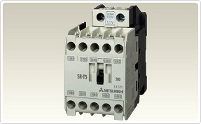
Contactor Relays

Improved contact reliability with twin contact points.
Can be used with DIN rails and for relay operation.
Product Specification
|
Specifications |
SR-T5 AC_ _ _ V 5A |
SR-T5 AC_ _ _ V 4A1B |
SR-T5 AC_ _ _ V 3A2B |
SRD-T5 DC24V 3A2B |
||
|---|---|---|---|---|---|---|
|
Contact arrangement |
5 NO |
4 NO + 1 NC |
3 NO + 2 NC |
3 NO + 2 NC |
||
|
Rated data |
||||||
|
Rated insulation voltage |
V |
690 |
690 |
690 |
690 |
|
|
Rated continuous current I th |
A |
16 |
16 |
16 |
16 |
|
|
Rated operating current; Category AC-15 (coil load) |
120 V |
A |
6 |
6 |
6 |
6 |
|
240 V |
A |
3 |
3 |
3 |
3 |
|
|
440 V |
A |
1.5 |
1.5 |
1.5 |
1.5 |
|
|
550 V |
A |
1.2 |
1.2 |
1.2 |
1.2 |
|
|
Rated operating current; Category AC-12 (coil load) |
120 V |
A |
10 |
10 |
10 |
10 |
|
240 V |
A |
8 |
8 |
8 |
8 |
|
|
440 V |
A |
5 |
5 |
5 |
5 |
|
|
550 V |
A |
5 |
5 |
5 |
5 |
|
|
Rated operating current; Category DC-13 (large coil load) |
24 V |
A |
3 |
5 |
5 |
5 |
|
48 V |
A |
1.5 |
3 |
3 |
3 |
|
|
110 V |
A |
0.6 (2) a |
0.6 (2) a |
0.6 (2) a |
0.6 (2) a |
|
|
220 V |
A |
0.3 (0.8) a |
0.3 (0.8) a |
0.3 (0.8) a |
0.3 (0.8) a |
|
|
Rated operating current; Category DC-12 (resistive load) |
24 V |
A |
10 |
10 |
10 |
10 |
|
48 V |
A |
8 |
8 |
8 |
8 |
|
|
110 V |
A |
5 (8) a |
5 (8) a |
5 (8) a |
5 (8) a |
|
|
220 V |
A |
1 (3) a |
1 (3) a |
1 (3) a |
1 (3) a |
|
|
Electrical data |
||||||
|
Coil consumption (at rated coil voltage) |
Inrush |
VA |
45 |
45 |
45 |
— |
|
Sealed |
VA |
7 |
7 |
7 |
— |
|
|
Watts |
W |
2.2 |
2.2 |
2.2 |
3.3 (2.2) |
|
|
Switching frequency |
Oper./h |
1,800 |
1,800 |
1,800 |
1,800 |
|
|
Operating time (average) |
Making |
ms |
15 |
15 |
15 |
50 |
|
Breaking |
ms |
10 |
10 |
10 |
10 |
|
|
Mechanical data |
||||||
|
Electrical life |
Oper. (million) |
0.5 |
0.5 |
0.5 |
0.5 |
|
|
Mechanical life |
10 |
10 |
10 |
10 |
||
|
Conductor size |
mm² |
1–2.5 |
1–2.5 |
1–2.5 |
1–2.5 |
|
|
Weight |
kg |
0.3 |
0.3 |
0.3 |
0.62 |
|
|
Dimensions (WxHxD) b |
mm |
43x78x78 |
43x78x78 |
43x78x78 |
43x78x110 |
|
|
Order information |
AC24V |
Art. no. |
279260 |
279267 |
279274 |
— |
|
AC 48V |
279261 |
279268 |
279275 |
— |
||
|
AC100V |
279262 |
279269 |
279276 |
— |
||
|
AC200V |
279263 |
279270 |
279277 |
— |
||
|
AC300V |
279264 |
279271 |
279278 |
— |
||
|
AC400V |
279265 |
279272 |
279279 |
— |
||
|
AC500V |
279266 |
279273 |
279280 |
— |
||
|
Order information |
DC24V |
Art. no. |
— |
— |
— |
287541 |
- Parenthesized rated operating current is for switching the load in 2-pole series connection.
- Dimensions on request.
Optional Parts and Accessories

There are many optional units for contactor relays.
Motor Protection Relays
Motor protection relays that protect your motor against burnout.
Can be used for protection against motor burnout during overload or locked rotor. Offers a wide range of functions, including protection against overload and phase loss, time lag, quick connect.
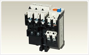
Motor Protection Relays without Phase Failure Protection

Protects motors against overload and locked rotor, securing safe operation.
Standard model complies with Japanese and many international standards.
Product Specification
|
Specifications |
TH-T18KP_ _ _ A |
TH-T25KP_ _ _ A |
TH-T50KP_ _ _ A |
TH-T65KP_ _ _ A |
TH-T100KP_ _ _ A |
TH-N120KP_ _ _ A |
TH-N120TAKP_ _ _ A |
TH-N220RHKP_ _ _ A |
TH-N400RHKP _ _ _ A |
TH-N600KP_ _ _ A a |
|||
|---|---|---|---|---|---|---|---|---|---|---|---|---|---|
|
Rated data |
|||||||||||||
|
Max. setting current |
A |
18 |
26 |
50 |
65 |
100 |
100 |
150 |
220 |
400 |
800 |
||
|
Range of setting current |
A |
0.12–18 |
0.24–26 |
24–50 |
12–65 |
54–100 |
34–100 |
85–150 |
65–250 |
85–400 |
200–800 |
||
|
Rated insulation voltage |
V |
690 |
690 |
690 |
690 |
690 |
690 |
690 |
1000 |
1000 |
690 |
||
|
Auxiliary contacts |
For all types: 1 NO + 1 NC |
||||||||||||
|
Max. heater dissipation per current path |
Min. settingW |
0.8 |
1.5 |
1.6 |
2.4 |
2.5 |
2.5 |
3.2 |
2.5 |
2.5 |
2.5 |
||
|
Max. settingW |
1.8 |
3.0 |
3.2 |
5.5 |
6.0 |
7.1 |
8.6 |
6.0 |
6.0 |
6.0 |
|||
|
Rated operating current of auxiliary contacts |
|||||||||||||
|
Category AC-15 |
NOcontact |
120 V |
A |
2 |
2 |
2 |
2 |
2 |
2 |
2 |
2 |
2 |
2 |
|
240 V |
A |
1 |
1 |
1 |
1 |
1 |
1 |
1 |
1 |
1 |
1 |
||
|
500 V |
A |
0.5 |
0.5 |
0.3 |
0.5 |
0.5 |
0.5 |
0.5 |
0.5 |
0.5 |
0.5 |
||
|
NCcontact |
120 V |
A |
2 |
3 |
3 |
3 |
3 |
3 |
3 |
3 |
3 |
3 |
|
|
240 V |
A |
1 |
2 |
2 |
2 |
2 |
2 |
2 |
2 |
2 |
2 |
||
|
500 V |
A |
0.5 |
1 |
0.3 |
1 |
1 |
1 |
1 |
1 |
1 |
1 |
||
|
Category DC-13 |
48 V |
A |
0.4 |
0.5 |
1 |
1 |
1 |
0.5 |
0.5 |
0.5 |
0.5 |
0.5 |
|
|
110 V |
A |
0.2 |
0.2 |
0.2 |
0.2 |
0.2 |
0.2 |
0.2 |
0.2 |
0.2 |
0.2 |
||
|
220 V |
A |
0.1 |
0.1 |
0.1 |
0.1 |
0.1 |
0.1 |
0.1 |
0.1 |
0.1 |
0.1 |
||
|
Sizes |
|||||||||||||
|
Main terminal screw size |
Line side |
mm |
— |
M4 |
M5 |
M6 |
M6 |
M8 |
M8 |
— |
— |
M4 |
|
|
Load size |
mm |
M3.5 |
M4 |
M5 |
M6 |
M6 |
M8 |
M8 |
M10 |
M12 |
M4 |
||
|
Max. conductorsize |
Main |
Line side |
mm² |
— |
6 |
14 |
38 |
60 |
— |
— |
6 |
||
|
Load side |
mm² |
2.5 |
6 |
14 |
38 |
60 |
70 |
240 |
6 |
||||
|
Busbar |
Line side |
mm |
— |
10.2 |
17 |
17 |
20 |
20 |
— |
— |
— |
||
|
Load side |
mm |
7.5 |
10.2 |
13.3 |
17 |
15 |
20 |
20 |
25 |
30 |
— |
||
|
Auxiliary contacts |
mm² |
2.5 |
2.5 |
2 |
2 |
2 |
4 |
4 |
4 |
4 |
4 |
||
|
Bimetal heating |
Direct |
Direct |
Direct |
Direct |
Direct |
Direct |
Direct |
Via CTs |
Via CTs |
Via CTs a |
|||
|
Weight |
kg |
0.11 |
0.16 |
0.2 |
0.26 |
0.32 |
0.48 |
0.75 |
2.5 |
2.7 |
0.14 |
||
|
Dimensions (WxHxD) |
mm |
45x55x76.5 |
63x51x69 |
74.3x72x83.5 |
89x57x83.5 |
89x73.5x83.5 |
103x67x105 |
112x87x105 |
144 x114 x180 |
144x160x194 |
63x42x83.5 |
||
|
Order information Art. no. |
See page <?> for order information |
||||||||||||
- Used with current transformer (to be supplied by the customer), for further information, see table on bottom of the page.
Optional Parts and Accessories

There are many optional units for motor protection relays.
Motor Circuit Breakers
Integration of Low Voltage Circuit Breakers and Thermal Overload Relay functions.
This device is capable of protecting motor branch circuits from overload, phase-loss, and short-circuit.
It offers even more secure wiring and motor protection.
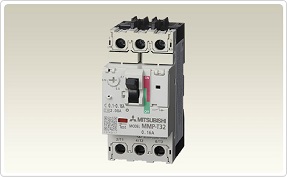
Motor Circuit Breakers

Space-saving design has lead to down-sizing of the control panel.
The rated short-circuit breaking capacity satisfies 10KA at a voltage of 200-240VAC.
Product Specification
|
Type name |
MMP–T32 |
MMP–T32LF |
||||||||||||
|---|---|---|---|---|---|---|---|---|---|---|---|---|---|---|
|
Standard |
JIS C8201-2-1 Ann.1, JIS 8201-4-1, EN60947-2, EN60947-4-1, IEC60947-2, IEC60947-4-1, GB14048.2 UL60947-4-1A, CSAC22.2NO.60947-4-1 |
EN60947-2, EN60947-4-1, IEC60947-2, IEC60947-4-1, GB14048.2 |
||||||||||||
|
Number of poles |
3 |
|||||||||||||
|
Handle shape |
Tumbler handle |
|||||||||||||
|
Rated current in [A] |
0.1 to 32 |
|||||||||||||
|
Rated operational voltage Ue [V] |
200 to 690 |
|||||||||||||
|
Rated frequency [Hz] |
50/60 |
|||||||||||||
|
Rated insulation voltage Ui [V] |
690 |
|||||||||||||
|
Rated impulse withstand voltage Uimp [kV] |
6 |
|||||||||||||
|
Rated short-circuit breaking capacity [kA] JIS C8201-2-1Ann.1 IEC60947-2 |
Rated current Ie [A] |
200/240 V |
400/415 V |
440/460 V |
200/240 V |
400/415 V |
440/460 V |
|||||||
|
Heater designation |
Current setting range |
lcu |
lcs |
lcu |
lcs |
lcu |
lcs |
lcu |
lcs |
lcu |
lcs |
lcu |
lcs |
|
|
0.16 |
0.1–0.16 |
100 |
100 |
100 |
100 |
100 |
100 |
|||||||
|
0.25 |
0.16–0.25 |
100 |
100 |
100 |
100 |
100 |
100 |
|||||||
|
0.4 |
0.25–0.4 |
100 |
100 |
100 |
100 |
100 |
100 |
|||||||
|
0.63 |
0.4–0.63 |
100 |
100 |
100 |
100 |
100 |
100 |
|||||||
|
1 |
0.63–1 |
100 |
100 |
100 |
100 |
100 |
100 |
|||||||
|
1.6 |
1–1.6 |
100 |
100 |
100 |
100 |
100 |
100 |
|||||||
|
2.5 |
1.6–2.5 |
100 |
100 |
100 |
100 |
100 |
100 |
|||||||
|
4 |
2.5–4 |
100 |
100 |
100 |
100 |
100 |
100 |
|||||||
|
6.3 |
4–6.3 |
100 |
100 |
100 |
100 |
100 |
50 |
50 |
||||||
|
8 |
5.5–8 |
100 |
100 |
50 |
38 |
100 |
100 |
15 |
15 |
|||||
|
10 |
7–10 |
100 |
100 |
50 |
38 |
100 |
100 |
15 |
15 |
|||||
|
13 |
9–13 |
100 |
100 |
50 |
38 |
100 |
15 |
7.5 |
8 |
4 |
||||
|
18 |
12–18 |
100 |
50 |
38 |
35 |
27 |
100 |
15 |
7.5 |
8 |
4 |
|||
|
25 |
18–25 |
100 |
50 |
38 |
35 |
27 |
50 |
15 |
6 |
6 |
3 |
|||
|
32 |
24–32 |
100 |
50 |
38 |
35 |
27 |
50 |
10 |
5 |
6 |
3 |
|||
|
Selectivity category |
JIS C8201-2-1 Ann.1 IEC60947-2 |
Cat.A |
||||||||||||
|
Utilization category |
JIS C8201-4-1 IEC60947-4-1 |
AC-3 |
||||||||||||
|
Trip class (JIS C8201-4-1, IEC60947-4-1) |
10 |
|||||||||||||
|
Instantaneous release current |
13 x Maximum Ie |
|||||||||||||
|
Durability |
Mechanical [times] |
100,000 |
||||||||||||
|
Electrical [times] |
100,000 |
|||||||||||||
|
Phase loss sensitive |
Yes |
|||||||||||||
|
Trip display |
Yes |
|||||||||||||
|
Test trip function |
Yes |
|||||||||||||
|
Auxiliary contact unit |
UT-MAX (1a or 1b) AC-12: 125 V/5 A, 250 V/3 A |
|||||||||||||
|
Alarm contact unit |
UT-MAL (1a or 1b) DC-12: 125 V/0.4 A, 250 V/0.2 A |
|||||||||||||
|
Short-circuit indicator unit |
UT-TU |
|||||||||||||
|
Weight [g] |
330 |
|||||||||||||
|
Breaking capacity at 415 V |
Current setting range |
Model |
Code |
|---|---|---|---|
|
100 KA |
0.1–0.16 A |
MMP-T32LF-0.16A |
288426 |
|
100 KA |
0.16–0.25 A |
MMP-T32LF-0.25A |
288427 |
|
100 KA |
0.25–0.4 A |
MMP-T32LF-0.4A |
288428 |
|
100 KA |
0.4–0.63 A |
MMP-T32LF-0.63A |
288429 |
|
100 KA |
0.6–1 A |
MMP-T32LF-1.0A |
288430 |
|
100 KA |
1–1.6 A |
MMP-T32LF-1.6A |
288431 |
|
100 KA |
1.6–2.5 A |
MMP-T32LF-2.5A |
288432 |
|
100 KA |
2.5–4 A |
MMP-T32LF-4.0A |
288433 |
|
100 KA |
4–6.3 A |
MMP-T32LF-6.3A |
288434 |
|
100 KA |
5.5–8 A |
MMP-T32LF-8A |
288435 |
|
100 KA |
7–10 A |
MMP-T32LF-10A |
288436 |
|
15 KA |
9–13 A |
MMP-T32LF-13A |
288437 |
|
15 KA |
12–18 A |
MMP-T32LF-18A |
288438 |
|
15 KA |
18–25 A |
MMP-T32LF-25A |
488439 |
|
10 KA |
24–32 A |
MMP-T32LF-32A |
288440 |
|
100 KA |
9–13 A |
MMP-T32-13A |
288441 |
|
50 KA |
12–18 A |
MMP-T32-18A |
288442 |
|
50 KA |
18–25 A |
MMP-T32-25A |
288443 |
|
50 KA |
24–32 A |
MMP-T32-32A |
288444 |
Optional Parts and Accessories

There are many optional units for motor circuit breakers.