Motor Protection Relays
Motor protection relays that protect your motor against burnout.
Can be used for protection against motor burnout during overload or locked rotor. Offers a wide range of functions, including protection against overload and phase loss, time lag, quick connect.
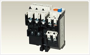
Motor Protection Relays without Phase Failure Protection

Protects motors against overload and locked rotor, securing safe operation.
Standard model complies with Japanese and many international standards.
Product Specification
|
Specifications |
TH-T18KP_ _ _ A |
TH-T25KP_ _ _ A |
TH-T50KP_ _ _ A |
TH-T65KP_ _ _ A |
TH-T100KP_ _ _ A |
TH-N120KP_ _ _ A |
TH-N120TAKP_ _ _ A |
TH-N220RHKP_ _ _ A |
TH-N400RHKP _ _ _ A |
TH-N600KP_ _ _ A a |
|||
|---|---|---|---|---|---|---|---|---|---|---|---|---|---|
|
Rated data |
|||||||||||||
|
Max. setting current |
A |
18 |
26 |
50 |
65 |
100 |
100 |
150 |
220 |
400 |
800 |
||
|
Range of setting current |
A |
0.12–18 |
0.24–26 |
24–50 |
12–65 |
54–100 |
34–100 |
85–150 |
65–250 |
85–400 |
200–800 |
||
|
Rated insulation voltage |
V |
690 |
690 |
690 |
690 |
690 |
690 |
690 |
1000 |
1000 |
690 |
||
|
Auxiliary contacts |
For all types: 1 NO + 1 NC |
||||||||||||
|
Max. heater dissipation per current path |
Min. settingW |
0.8 |
1.5 |
1.6 |
2.4 |
2.5 |
2.5 |
3.2 |
2.5 |
2.5 |
2.5 |
||
|
Max. settingW |
1.8 |
3.0 |
3.2 |
5.5 |
6.0 |
7.1 |
8.6 |
6.0 |
6.0 |
6.0 |
|||
|
Rated operating current of auxiliary contacts |
|||||||||||||
|
Category AC-15 |
NOcontact |
120 V |
A |
2 |
2 |
2 |
2 |
2 |
2 |
2 |
2 |
2 |
2 |
|
240 V |
A |
1 |
1 |
1 |
1 |
1 |
1 |
1 |
1 |
1 |
1 |
||
|
500 V |
A |
0.5 |
0.5 |
0.3 |
0.5 |
0.5 |
0.5 |
0.5 |
0.5 |
0.5 |
0.5 |
||
|
NCcontact |
120 V |
A |
2 |
3 |
3 |
3 |
3 |
3 |
3 |
3 |
3 |
3 |
|
|
240 V |
A |
1 |
2 |
2 |
2 |
2 |
2 |
2 |
2 |
2 |
2 |
||
|
500 V |
A |
0.5 |
1 |
0.3 |
1 |
1 |
1 |
1 |
1 |
1 |
1 |
||
|
Category DC-13 |
48 V |
A |
0.4 |
0.5 |
1 |
1 |
1 |
0.5 |
0.5 |
0.5 |
0.5 |
0.5 |
|
|
110 V |
A |
0.2 |
0.2 |
0.2 |
0.2 |
0.2 |
0.2 |
0.2 |
0.2 |
0.2 |
0.2 |
||
|
220 V |
A |
0.1 |
0.1 |
0.1 |
0.1 |
0.1 |
0.1 |
0.1 |
0.1 |
0.1 |
0.1 |
||
|
Sizes |
|||||||||||||
|
Main terminal screw size |
Line side |
mm |
— |
M4 |
M5 |
M6 |
M6 |
M8 |
M8 |
— |
— |
M4 |
|
|
Load size |
mm |
M3.5 |
M4 |
M5 |
M6 |
M6 |
M8 |
M8 |
M10 |
M12 |
M4 |
||
|
Max. conductorsize |
Main |
Line side |
mm² |
— |
6 |
14 |
38 |
60 |
— |
— |
6 |
||
|
Load side |
mm² |
2.5 |
6 |
14 |
38 |
60 |
70 |
240 |
6 |
||||
|
Busbar |
Line side |
mm |
— |
10.2 |
17 |
17 |
20 |
20 |
— |
— |
— |
||
|
Load side |
mm |
7.5 |
10.2 |
13.3 |
17 |
15 |
20 |
20 |
25 |
30 |
— |
||
|
Auxiliary contacts |
mm² |
2.5 |
2.5 |
2 |
2 |
2 |
4 |
4 |
4 |
4 |
4 |
||
|
Bimetal heating |
Direct |
Direct |
Direct |
Direct |
Direct |
Direct |
Direct |
Via CTs |
Via CTs |
Via CTs a |
|||
|
Weight |
kg |
0.11 |
0.16 |
0.2 |
0.26 |
0.32 |
0.48 |
0.75 |
2.5 |
2.7 |
0.14 |
||
|
Dimensions (WxHxD) |
mm |
45x55x76.5 |
63x51x69 |
74.3x72x83.5 |
89x57x83.5 |
89x73.5x83.5 |
103x67x105 |
112x87x105 |
144 x114 x180 |
144x160x194 |
63x42x83.5 |
||
|
Order information Art. no. |
See page <?> for order information |
||||||||||||
- Used with current transformer (to be supplied by the customer), for further information, see table on bottom of the page.
Optional Parts and Accessories

There are many optional units for motor protection relays.